PCB materials are divided into technical substrates and composite substrates, usually divided into copper substrates, aluminum substrates, fiberglass boards, epoxy resins, etc. Different materials differs in lasers and laser processing methods. For example, copper substrates and aluminum substrates usually use QCW or continuous infrared laser cutting machines, and use focusing heads for penetrating processing, assisted by auxiliary gases (nitrogen, oxidation, argon, air) for processing, while non-metallic materials such as fiberglass boards are usually processed by green laser cutting machines and UV laser cutting machines.
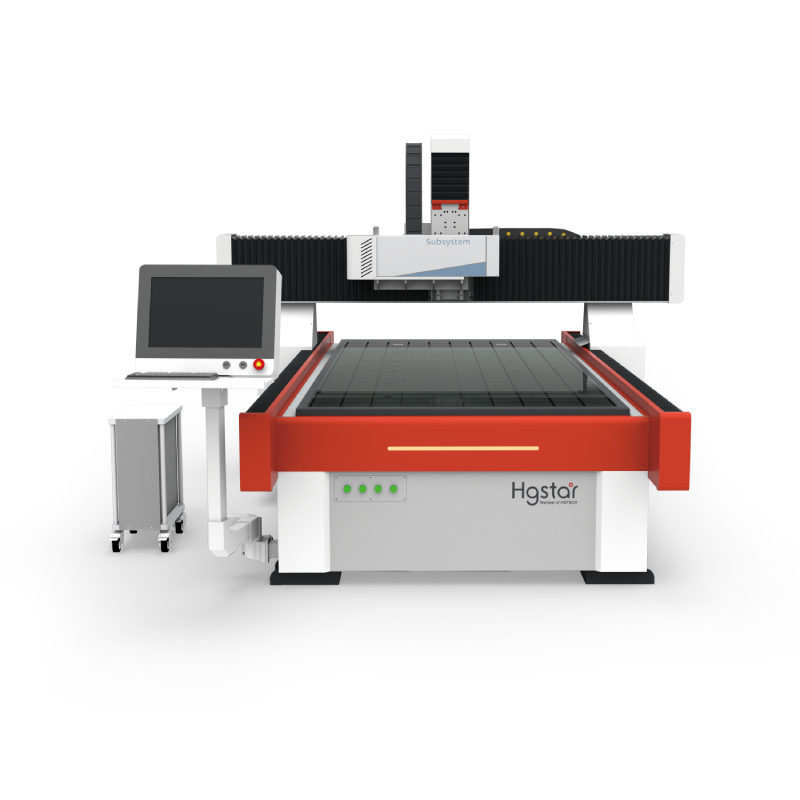
UV laser cutting PCB equipment refers to the use of 355nm UV lasers, which are focused by optical devices such as beam expanders, galvanometers, and focusing mirrors to form a light spot less than 20 microns. The galvanometer XY motor deflection is controlled by software, and the light spot moves within the scanning range of the focusing mirror. By controlling the movement of the light spot, it scans over and over again within a certain area, peeling off the material surface layer by layer, thereby achieving the purpose of cutting the material. If the scanning range of the lens is exceeded, it is necessary to control the XY linear motor of the material placement platform to move and splice the material. The gantry structure or XY platform structure is selected according to the size of the material. Usually, the focal length of the Z-axis linear motor is adjusted according to the thickness of the material. The focal depth of the UV laser cutting machine is relatively short, and the focal length needs to be adjusted at any time according to the processing needs. For example, the focal length difference needs to be adjusted when cutting FPC flexible circuit boards and cutting 2mm hard boards.
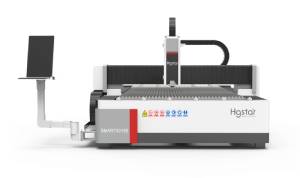
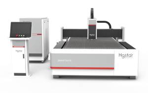
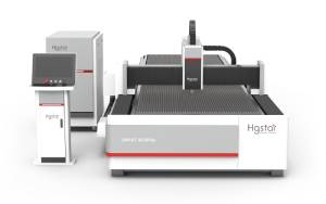
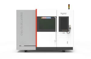
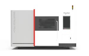
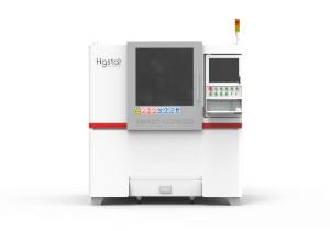
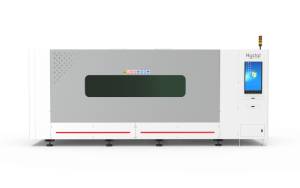
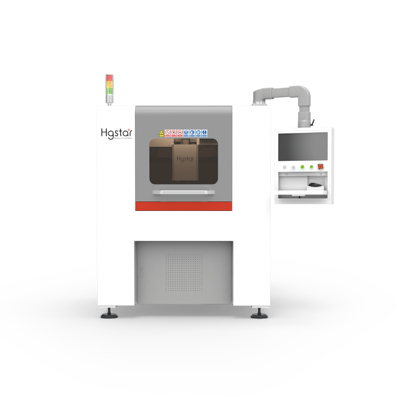
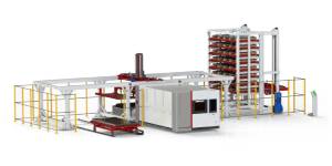
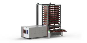
The UV laser cutting machine is a complete set of integrated equipment for optomechanical information. The equipment structure consists of UV laser, XY linear table, driver, industrial computer, high-speed galvanometer, system control software, positioning system, dust extraction system, vacuum adsorption system, external optical path, machine, etc.
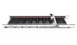
The size of the stand-alone UV laser cutting machine is theoretically unlimited and can be customized according to the needs of the customer. Usually, the standard processing size is within the range of 400*300mm and 500*400mm. Of course, the specifications of each manufacturer are slightly different.
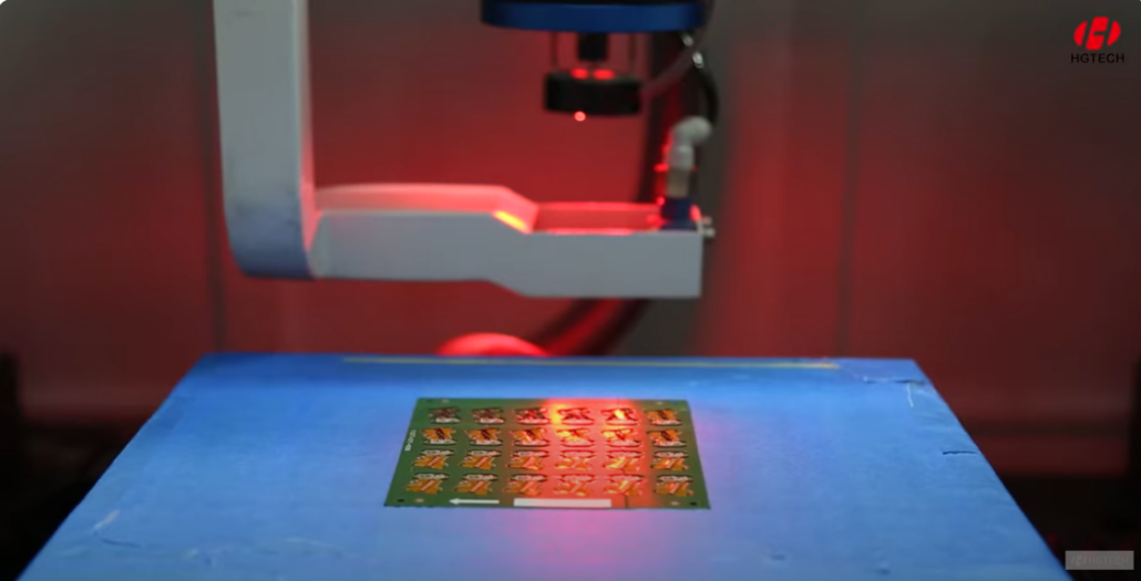
UV laser cutting PCB effect
The effect of UV laser cutting PCB is closely related to the parameters of the laser, optical path devices, processing speed and other conditions. Usually, the UV laser cutting machine is required to have high frequency, narrow pulse width, high single pulse energy, and high-precision devices as much as possible for external optical path devices. UV laser cutting PCB usually has slight carbonization on the cutting section, but it does not affect its conductive properties. If you want to completely eliminate carbonization, you need to reduce the cutting speed to achieve it, and the customer needs to have a balance.
UV laser cutting PCB speed
The cutting speed of UV laser is closely related to power, material thickness, etc., and the cutting effect must also be taken into account. Generally speaking, the higher the power of the UV laser, the faster the cutting speed, and the thinner the thickness, the faster the cutting speed.
How far can the cutting speed reach in one second? Can it reach the speed of 80mm/s of the milling cutter?
UV laser cutting PCB is not direct penetration cutting, but scanning and peeling processing. For example, using an 18W laser, a 100mm lens, and cutting 0.8mm FR4, the cutting speed is usually between 20-30mm/s. The specific algorithm is an estimated value. For example, 100mm FR4 needs to be cut, scanned 30 times, using 80% power, and a cutting speed of 3000mm/s, then the converted cutting speed is 30mm/s. The actual cutting speed needs to be determined based on test proofing. These speeds can only be used as a reference, not as an actual indicator. A more reasonable indicator is: calculate the processing speed based on the processing beat of each small piece in each batch. It is necessary to take into account comprehensive factors such as production line beat, processing effect, and calculation equipment cost.
Price issues have always been a commonplace issue, and the decision is in the hands of the customer. HGLASER’s professional engineers can help customers choose models, develop product lines with customers, and provide solutions. Customers need to have a budget target after inspection, and decide based on actual needs, while taking into account issues such as service life and maintenance costs.